MEP systems sit at the center of every modern building project. Mechanical, electrical, and plumbing networks share tight ceiling voids, congested wall chases, and limited service corridors. A single misaligned duct or pipe run creates field conflicts that cost teams time, labor, and budget they cannot recover easily.
Traditional workflows make that risk worse. Engineers design against outdated drawings. Field crews rely on manual tape measurements that miss hidden conditions. Coordination gaps appear late after procurement, after fabrication, and after installation begins. The result is a cycle of RFIs, change orders, and costly rework that slows every project stage.
That gap explains why MEP teams now treat spatial accuracy as a prerequisite, not an afterthought. Projects that anchor design decisions in verified, real-world conditions move faster, coordinate better, and deliver fewer field surprises across every trade.
What Is Scan to BIM for MEP Engineering?
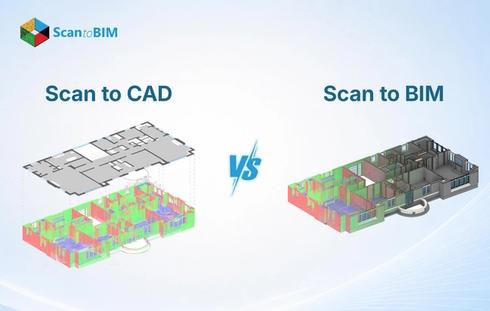
Scan to MEP BIM converts 3D laser scan point clouds into fully intelligent, construction-ready Revit MEP models. Surveyors deploy terrestrial or mobile LiDAR scanners across a building. With millimeter-level accuracy, the scanners capture millions of precise data points. Those points form a complete spatial map of the point cloud of every ceiling, wall, floor, column, and existing service. MEP modelers then trace mechanical, electrical, and plumbing systems directly over that spatial data inside Revit. The resulting model carries actual dimensions, real elevations, and verified clearances from the physical building. That distinction changes how MEP teams approach every stage of project delivery.
Why Traditional MEP Workflows Fall Short
Most legacy MEP workflows carry three connected problems. They start with incomplete data, move into uncoordinated design, and land in expensive field conflicts. Each stage makes the next one harder to manage.
Outdated floor plans
Site drawings age quickly. After even a few renovation cycles, the dimensions on paper stop matching what the building actually contains. Engineers who design against those numbers build in errors from the start.
Manual site measurements
A field team with a laser distance meter covers the accessible areas well. Congested plant rooms, ceiling voids above occupied spaces, and internal wall chases often go unmeasured. Those unmeasured zones are precisely where MEP routing conflicts tend to appear later.
Late clash discovery
Without a coordinated 3D model, MEP trades discover conflicts on site. Duct routes collide with structural beams. Pipe runs hit conduit clusters. Each conflict triggers redesign, procurement changes, and rework labor.
Change order accumulation
Two duct runs fighting for the same 150mm of ceiling clearance look fine on separate 2D drawings. Inside a shared 3D environment, that conflict becomes visible immediately. On projects without 3D coordination, the same conflict shows up when an installer physically runs out of space on site weeks into the job.
These problems compound on renovation programs and retrofit assignments. Existing conditions stay unknown until workers physically open walls and ceilings long after design decisions lock in.
How Scan to BIM Streamlines MEP Design and Construction
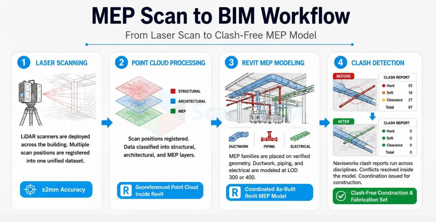
MEP Scan to BIM modeling replaces assumptions with verified spatial data at the earliest project stage. Laser scanning crews capture the entire building in a single mobilization. They register multiple scan positions into one unified point cloud. MEP modelers receive that dataset directly inside Revit. They extract ceiling clearances, structural offsets, and existing service routes from real geometry without returning to site for additional measurements. Design decisions land on verified conditions from day one.
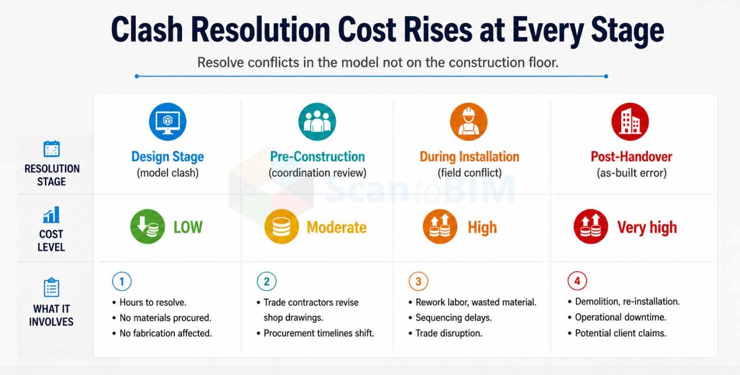
Coordination across trades improves from that point forward. Mechanical engineers pull confirmed ceiling void dimensions before sizing ductwork. Electrical designers work around structural members they can actually see in the point cloud, not ones they assumed were there. Plumbing engineers size pipe runs against real floor-to-ceiling heights rather than against spec sheet estimates. Every discipline draws from the same spatial reference. Clashes that would have appeared during installation surface during design review instead, where they take hours to fix rather than days.
Key Benefits of Scan to BIM in MEP Projects
Scan to BIM technology delivers measurable improvements across the full MEP project lifecycle:
- Verified as-built conditions: Point cloud data captures every existing structural element and service with millimeter accuracy. Design teams stop working from assumptions and start working from measured reality.
- Faster design production: Revit MEP modeling starts immediately after point cloud delivery. No return site visits. No manual measurement reconciliation. Drawing cross-checks becomes a ten-minute model review rather than a two-week process.
- Reduced coordination conflicts: Clash detection inside Revit catches MEP conflicts during the design phase. A conflict caught at this stage costs a fraction of what the same conflict costs after fabrication begins.
- Fabrication-ready geometry: Ductwork sections, piping spools, and electrical assemblies can go to the fabricator directly from the model. Dimensions are verified. Surprises on the shop floor drop significantly.
- Renovation project clarity: Retrofit designers get a complete picture of every hidden service before demolition begins. Sequencing, phasing, and scope all get set against real data not against what the old drawings suggest might be there.
- Facility management continuity: Most facilities teams inherit a set of PDFs and hope nothing changes. An as-built Revit model gives them live spatial data instead pipe routes, equipment specs, and maintenance access points, all in one place.
- Compliance documentation: Permit and inspection stages go more smoothly when engineers can show accurate model geometry with verified clearance dimensions rather than hand-sketched site notes.
The Role of Point Cloud Data in Accurate MEP Modeling
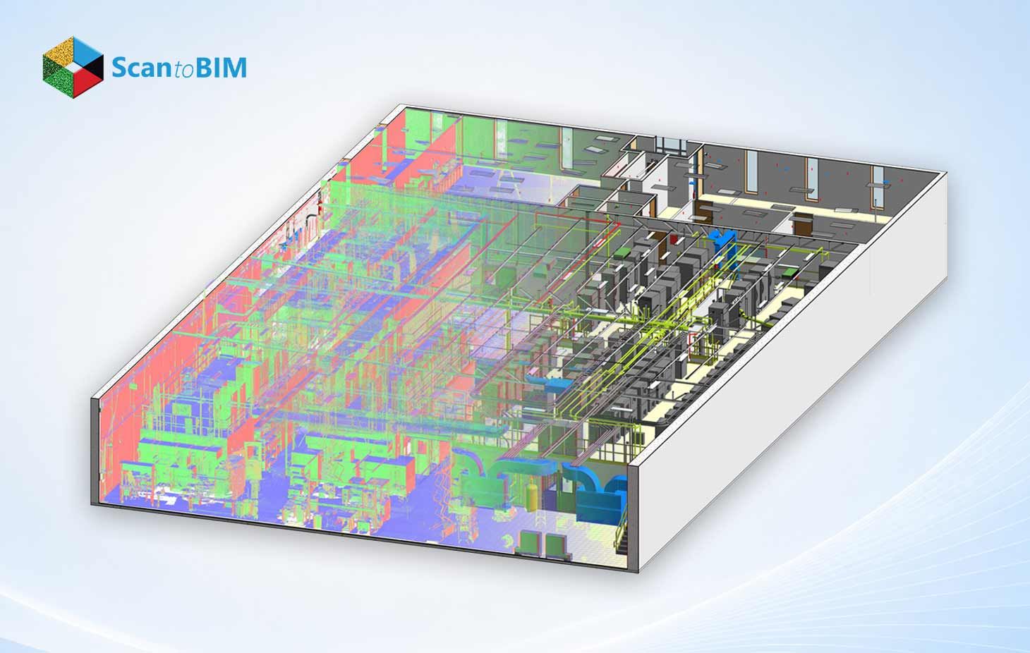
Every MEP model is only as accurate as the spatial data behind it. LiDAR scanners used for point cloud capture operate at professional survey grade. Modern terrestrial scanners capture up to 2 million data points per second. Mobile mapping systems allow crews to scan entire floors in a single continuous pass. The raw output is a precise 3D representation of the building as it physically stands, every beam, column, ceiling void, and existing service included.
Inside Revit, modelers use this point cloud reference to place MEP families at exact, verified coordinates. HVAC air handling units land at their true locations. Pipe headers run at actual elevations. Electrical panel boards sit at confirmed wall positions. Every model element traces back to a measured data point, not an assumed dimension.
AI-assisted classification tools have added another layer of speed to this process. Algorithms now sort point cloud data into structural, architectural, and MEP layers automatically rather than waiting for modelers to categorize everything by hand. That shift lets experienced modelers spend their time on coordination decisions and quality review of the work that actually requires judgment.
Improving MEP Coordination and Clash Detection
MEP clash detection using Scan to BIM identifies spatial conflicts between disciplines inside the BIM environment before physical work begins. Revit's coordination tools flag hard clashes where elements physically intersect and soft clashes. Where clearance minimums fall short of code or installation requirements. Autodesk Navisworks takes that coordination further. Clash detection reports list every conflict by discipline pair, location, and severity level. Design teams work through those reports systematically.
They adjust duct routes, repipe offsets, and reroute conduit runs inside the model. Each resolved clash saves measurable field labor. Coordinated MEP models also support prefabrication programs directly. Shop-fabricated ductwork and piping spools arrive on site, cut to exact lengths because the spatial data behind them is accurate. That accuracy eliminates the field cutting, fitting adjustments, and installation delays that fabrication errors produce on traditional projects.
Real-World Applications of Scan to BIM in MEP Projects
MEP laser scanning services apply across project types where existing spatial conditions carry risk.
Hospital Retrofits
Healthcare facilities add new mechanical and electrical systems around active clinical operations. Laser scanning for MEP captures congested ceiling conditions above patient wards without disrupting care. Engineers design around real obstructions, fire suppression mains, medical gas lines, and existing HVAC infrastructure without opening a single ceiling tile.
Educational Building Upgrades
A 29,000 sq ft educational building Scan to BIM project demonstrated how full MEP documentation provides retrofit designers with a complete spatial inventory. Engineers confirmed ceiling space for new HVAC distribution, planned electrical upgrades around existing conduit runs, and verified plumbing riser locations, all from point cloud data, before any design work began.
Airport and Transport Infrastructure
Large-scale airport projects cover millions of square feet of terminal space. Engineers coordinate complex HVAC zoning, electrical distribution, and plumbing across multiple building levels using accurate as-built spatial data. Coordination at this scale demands verified geometry manual measurements cannot cover the required area with acceptable accuracy.
Commercial Office Fit-Outs
MEP renovation projects in occupied office buildings demand minimal disruption. Point cloud capture happens over a single weekend. MEP design proceeds the following week with a complete digital model of existing fit-out conditions no second site visit required.
Industrial Facility Retrofits
Plant retrofits require MEP engineers to navigate dense existing pipe racks, cable routes, and equipment platforms. Point cloud data maps every existing element in three dimensions. New process piping and electrical upgrades route through confirmed open corridors rather than assumed ones.
Best Practices for Successful Scan to BIM Adoption
Teams that treat scan to BIM as a structured workflow, not just a technology tool, consistently deliver better coordination outcomes.
- Define LOD requirements before scanning: Establish level of detail requirements for the Revit MEP model before mobilization. LOD 300 suits design coordination. LOD 400 supports fabrication and shop drawing production.
- Plan scan positions with the MEP team: A pre-scan walkthrough identifies problem areas: restricted access zones, ceiling spaces that need special equipment, and plant rooms where scan positions need careful planning. Problems caught here cost nothing. Problems discovered mid-scan cost time.
- Match scan density to coordination complexity: High-traffic MEP coordination zones need denser scan grids. Open floor plates need fewer positions. Aligning scan density with coordination requirements controls both cost and deliverable quality.
- Use a Common Data Environment: Store point clouds, Revit models, and clash reports on one shared platform. Every discipline accesses the same current version. Version confusion and file duplication disappear.
- Run phased clash detection: Address discipline-internal clashes first. Mechanical self-clash, then electrical. Then run inter-discipline coordination reviews. Phased reviews produce cleaner coordination meetings with faster resolution cycles.
- Validate model accuracy before release: Before a Revit model goes out for construction, spot-check critical element positions against the source point cloud. Equipment locations, clearance zones, and coordination-sensitive ceiling spaces all deserve a direct comparison between the model and the measured data.
- Engage MEP subcontractors during coordination: Trade contractors reviewing a coordinated model before procurement finalizes can flag constructability concerns that office-based coordination reviews miss. Their site experience adds a layer of review that no clash detection algorithm replicates.
Choosing a Reliable Scan to BIM Partner
Finding the right MEP laser scanning services partner means looking at two things together field scanning capability and MEP modeling depth. A high-accuracy point cloud paired with a modeling team that cannot interpret complex MEP layouts produces a model that looks complete but carries coordination gaps. Ask partners directly about their LOD delivery history, their turnaround timelines on projects similar in size, and how familiar their modelers are with local code requirements for MEP clearances and service coordination. Request sample Revit files and compare model content against the source point cloud they came from.
A strong Scan to BIM partner also communicates clearly at every stage of the project. They flag scan access issues immediately. They raise modeling questions before those questions affect delivery schedules. They deliver clash detection reports in formats that the coordination team uses, such as Navisworks, BIM 360, or Revit coordination views, rather than in generic exports that require reformatting. The right partner contributes genuine technical value from scan planning through model handover and stands behind the spatial accuracy of every delivered file.
Conclusion
MEP projects succeed when design decisions connect directly to real building conditions. Scan to BIM provides engineering teams with a connection that spans from the earliest coordination stage through construction, fabrication, and facilities handover. Laser scanning removes spatial uncertainty before design begins. Revit MEP modeling turns verified point cloud data into coordinated, construction-ready intelligence. Clash detection resolves conflicts at design cost rather than field cost. As-built documentation supports operations teams for the full lifecycle of the building. Teams that adopt this workflow deliver MEP projects with greater spatial confidence, fewer field surprises, and stronger coordination outcomes across every discipline.